
Content
Table of Contents
0. Background information
Recommended
-
For an introduction to kata, you can read this: https://blog.csdn.net/m0_46700908/article/details/125527520
-
Then there is kata’s github. If you want to try it, you can follow the documentation, and its docs directory also has a lot of instructions: https://github.com/kata-containers/kata-containers
-
This is a Chinese tutorial written by a Chinese developer of kata. If you want to learn more about kata’s architecture and source code, you can read it. He didn’t finish it, but some of the content is still very useful: http://liubin.org/kata-dev-book/
1. Question
-
How does traffic flow from k8s to the container?
-
How does the host communicate with the virtual machine?
There are two different ways for processes in the virtual machine to communicate with processes in the host. The first is by using serial ports. The process in the VM can read/write data from the serial port device, and the process in the host can read/write data from the Unix socket.
-
How does the VM communicate with the pod?
-
How does the pod communicate with the container?
-
How do multiple containers in a pod communicate?
kata-agent communicates with other kata components via gRPC.
Communication mechanism:
//Serial port, multiplexing mechanism
.----------------------.
| .------------------. |
| | .-----. .-----. | |
| | |cont1| |cont2| | |
| | `-----' `-----' | |
| | \ / | |
| | .---------. | |
| | | agent | | |
| | `---------' | |
| | | | |
| | .-----------. | |
| |POD |serial port| | |
| `----|-----------|-' |
| | socket | |
| `----------' |
| | |
| .------. |
| | proxy | |
| `-------' |
| | |
| .------./ \.------. |
| | shim | | shim | |
| `------' `------' |
| Host |
`---------------------'

//vsock communication
.------------------------.
| .------------------. |
| | .-----. .-----. | |
| | |cont1| |cont2| | |
| | `-----' `-----' | |
| | | | | |
| | .---------. | |
| | | agent | | |
| | `---------' | |
| | | | | |
| | POD .-------. | |
| `-----| vsock |----' |
| `-------' |
| | | |
| .------. .------. |
| | shim | | shim | |
| `------' `------' |
| Host |
`---------------------'
- how to run Kata Containers with kubernetes
https://github.com/kata-containers/documentation/blob/master/how-to/run-kata-with-k8s.md
- How to use vgpu in kata containers
https://github.com/kata-containers/documentation/blob/master/use-cases/Nvidia-GPU-passthrough-and-Kata.md
Nvidia GPU pass-through mode, an entire physical GPU is directly assigned to one VM, bypassing the Nvidia Virtual GPU Manager. In this mode of operation, the GPU is accessed exclusively by the Nvidia driver running in the VM to which it is assigned. The GPU is not shared among VMs.
Nvidia Virtual GPU (vGPU) enables multiple virtual machines (VMs) to have simultaneous, direct access to a single physical GPU, using the same Nvidia graphics drivers that are deployed on non-virtualized operating systems. By doing this, Nvidia vGPU provides VMs with unparalleled graphics performance, compute performance, and application compatibility, together with the cost-effectiveness and scalability brought about by sharing a GPU among multiple workloads.
-
Shim interlayer, who is responsible for interaction with whom?
-
Runc is also a mezzanine, responsible for software and hardware interaction?
-
Runtime implements CRI, so who implements OCI? What is the specific form of OCI?
OCI officially implemented a solution based on the runtime specification, called Runc.
2. Several concepts (understand the role and function of each component from the architectural level)
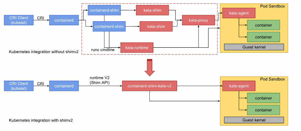
2.1 Communication between k8s and Kata containers
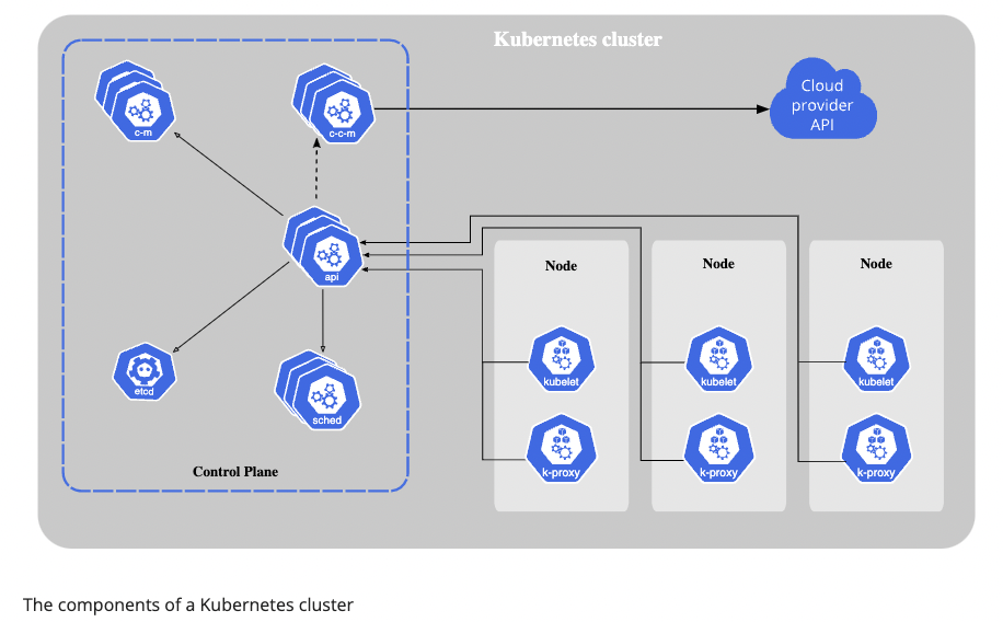
The K8s cluster creates multiple Node nodes, each of which contains Kubelet and kube-proxy. Kubelet is the CRI client, calling the gRPC server method of CRI to create a specific pod. The second picture actually shows Server-side implementation of CRI.
2.2 k8s components
Control Plane
The container orchestration layer that exposes the API and interfaces to define, deploy, and manage the lifecycle of containers.
The control plane’s components make global decisions about the cluster (for example, scheduling), as well as detecting and responding to cluster events (for example, starting up a new pod when a deployment’s replicas field is unsatisfied).
Control plane components can be run on any machine in the cluster. However, for simplicity, set up scripts typically start all control plane components on the same machine, and do not run user containers on this machine. See Creating Highly Available clusters with kubeadm for an example control plane setup that runs across multiple machines.
- Kube-apiserver
The API server is the front end for the Kubernetes control plane.
*etcd
Consistent and highly-available key value store used as Kubernetes’ backing store for all cluster data.
- Kube-scheduler
Control plane component that watches for newly created Pods with no assigned node, and selects a node for them to run on.
- Kube-controller-manager
Control plane component that runs controller processes.
Logically, each controller is a separate process, but to reduce complexity, they are all compiled into a single binary and run in a single process.
- Cloud-controller-manager
The cloud controller manager lets you link your cluster into your cloud provider’s API, and separates out the components that interact with that cloud platform from components that only interact with your cluster.
The cloud-controller-manager only runs controllers that are specific to your cloud provider. If you are running Kubernetes on your own premises, or in a learning environment inside your own PC, the cluster does not have a cloud controller manager.
Node Components
- kubelet
An agent that runs on each node in the cluster. It makes sure that containers are running in a Pod. The kubelet takes a set of PodSpecs that are provided through various mechanisms and ensures that the containers described in those PodSpecs are running and healthy. The kubelet doesn’t manage containers which were not created by Kubernetes.
- Kube-proxy
kube-proxy is a network proxy that runs on each node in your cluster, implementing part of the Kubernetes Service concept. kube-proxy maintains network rules on nodes. These network rules allow network communication to your Pods from network sessions inside or outside of your cluster.
- Container runtime
The container runtime is the software that is responsible for running containers. Kubernetes supports container runtimes such as containerd, CRI-O, and any other implementation of the Kubernetes CRI (Container Runtime Interface).
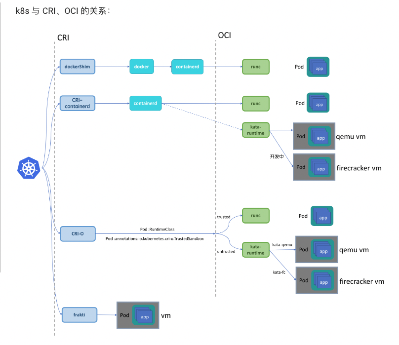
2.3 CRI and OCI
CRI
Container Runtime Interface. The Container Runtime Interface (CRI) is the main protocol for the communication between the kubelet and Container Runtime. kubelet and container runtime.
In other words, Kubelet is the CRI client (running gRPC-client), and various runtimes (e.g. containerd, CRI-O) implement the CRI server.
- Containerd
Support OCI images
Support OCI runtime (Runc)
Support image pull/push operations
Container runtime and lifecycle management
Network primitives: create/modify/delete interfaces
Add containers to existing Network Namespaces
Use “content addressable” storage to support global image multi-tenant sharing
-
CRI-O
- Docker Engine
- Mirantis Container Runtime
known as Docker Enterprise Edition.
####OCI
Open Containers Initiative includes three specifications that govern finding, running, building and sharing containers.
Image Spec: used to standardize image format;
Runtime Spec: It specifies how to control the container, including operations of the container life cycle, such as create/delete/start/stop; the implementation scheme can be found on Github: https://github.com/opencontainers/runtime-spec/blob/main/implementations.md,
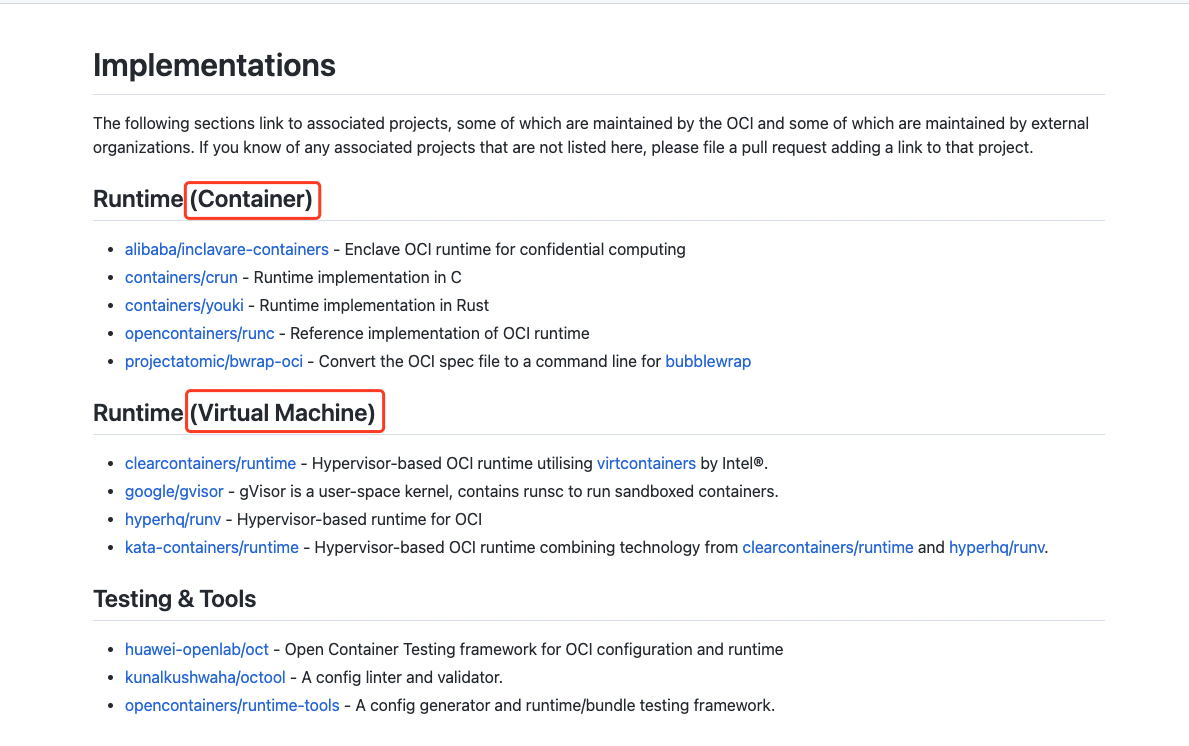
It is mainly divided into two implementation methods: container and VM. Runc implements the container mode, and kata-runtime implements the VM mode.
- runc
runc is a CLI tool for spawning and running containers according to the OCI specification.
OCI officially implemented an OCI solution, Runc
- kata-runtime
Kata Containers runtime (kata-runtime) is compatible with OCI runtime specification, which is at the same level as runc. So it can be used to replace the default runtime runc of docker.
difference between Containerd and Runc
containerd is called a high-level container runtime. For some actions, it makes use of yet another runtime, called a low-level container runtime. This low-level runtime is called runc. For example, when containerd needs to start a container, it tells runc to do that.
- Why not use containerd to start the container directly, but call runc instead?
3. How to call different resources (how resources are called from the perspective of traffic)
How does the network go? After the service is deployed, a request enters the backend, and traffic forwards.
cpu resources?
How to use gpu resources? vgpu or physical GPU, start a gpu job, how does the controller call for the gpu resource.
SR-IOV and IO virtualization
3.1 Cgroups
control group. related to CPU, memory, i/o.
Both kubelet and the underlying container runtime need to interface with control groups to enforce resource management for pods and containers and set resources such as cpu/memory requests and limits. To interface with control groups, the kubelet and the container runtime need to use a cgroup driver. It’s critical that the kubelet and the container runtime uses the same cgroup driver and are configured the same.
- Configuring the kubelet cgroup driver
cgroupDriver: systemd
Introdcution
Cgroups allow you to allocate resources — such as CPU time, system memory, network bandwidth, or combinations of these resources — among user-defined groups of tasks (processes) running on a system.
Cgroups are similar to processes in that:
- they are hierarchical, and
- child cgroups inherit certain attributes from their parent cgroup.
The fundamental difference is that many different hierarchies of cgroups can exist simultaneously on a system. If the Linux process model is a single tree of processes, then the cgroup model is one or more separate, unconnected trees of tasks (i.e. processes).
Multiple separate hierarchies of cgroups are necessary because each hierarchy is attached to one or more subsystems. A subsystem represents a single resource, such as CPU time or memory. Red Hat Enterprise Linux 6 provides ten cgroup subsystems.
Subsystems
- blkio
Block I/O
The Block I/O ( blkio ) subsystem controls and monitors access to I/O on block devices by tasks in cgroups. Writing values to some of these pseudofiles limits access or bandwidth, and reading values from some of these pseudofiles provides information on I/O operations.
*CPU
The cpu subsystem schedules CPU access to cgroups. Access to CPU resources can be scheduled using two schedulers:
Completely Fair Scheduler (CFS) — a proportional share scheduler which divides the CPU time (CPU bandwidth) proportionately between groups of tasks (cgroups) depending on the priority/weight of the task or shares assigned to cgroups. For more information about resource limiting using CFS, refer to Section 3.2.1, “CFS Tunable Parameters”.
Real-Time scheduler (RT) — a task scheduler that provides a way to specify the amount of CPU time that real-time tasks can use. For more information about resource limiting of real-time tasks, refer to Section 3.2.2, “RT Tunable Parameters”.
- cpuacct
CPU Accounting
The CPU Accounting (cpuacct) subsystem generates automatic reports on CPU resources used by the tasks in a cgroup, including tasks in child groups.
*cpuset
The cpuset subsystem assigns individual CPUs and memory nodes to cgroups. Each cpuset can be specified according to the following parameters, each one in a separate pseudofile within the cgroup virtual file system.
*devices
The devices subsystem allows or denies access to devices by tasks in a cgroup.
*freezer
The freezer subsystem suspends or resumes tasks in a cgroup.
*memory
The memory subsystem generates automatic reports on memory resources used by the tasks in a cgroup, and sets limits on memory use of those tasks.
- net_cls
The net_cls subsystem tags network packets with a class identifier (classid) that allows the Linux traffic controller (tc) to identify packets originating from a particular cgroup. The traffic controller can be configured to assign different priorities to packets from different cgroups.
- net_prio
The Network Priority (net_prio) subsystem provides a way to dynamically set the priority of network traffic per each network interface for applications within various cgroups. A network’s priority is a number assigned to network traffic and used internally by the system and network devices. Network priority is used to differentiate packets that are sent, queued, or dropped.
*ns
The ns subsystem provides a way to group processes into separate namespaces. Within a particular namespace, processes can interact with each other but are isolated from processes running in other namespaces. These separate namespaces are sometimes referred to as containers when used for operating-system-level virtualization.
3.2 kata container structure
kata-agent
kata-agent is a process running in the guest as a supervisor for managing containers and processes running within those containers.
The kata-agent execution unit is the sandbox. A kata-agent sandbox is a container sandbox defined by a set of namespaces (NS, UTS, IPC and PID). kata-runtime can run several containers per VM to support container engines that require multiple containers running inside a pod. In the case of docker, kata-runtime creates a single container per pod.
Runtime
kata-runtime is an OCI compatible container runtime and is responsible for handling all commands specified by the OCI runtime specification and launching kata-shim instances.
Proxy
Communication with the VM can be achieved by either virtio-serial or, if the host kernel is newer than v4.8, a virtual socket, vsock can be used. The default is virtio-serial.
The VM will likely be running multiple container processes. In the event virtio-serial is used, the I/O streams associated with each process needs to be multiplexed and demultiplexed on the host. On systems with vsock support, this component becomes optional.
kata-proxy is a process offering access to the VM kata-agent to multiple kata-shim and kata-runtime clients associated with the VM. Its main role is to route the I/O streams and signals between each kata-shim instance and the kata-agent. kata-proxy connects to kata-agent on a Unix domain socket that kata-runtime provides while spawning kata-proxy. kata-proxy uses yamux to multiplex gRPC requests on its connection to the kata-agent.
When proxy type is configured as proxyBuiltIn, we do not spawn a separate process to proxy gRPC connections. Instead a built-in Yamux gRPC dialer is used to connect directly to kata-agent. This is used by CRI container runtime server frakti which calls directly into kata-runtime.
Shim
A container process reaper, such as Docker’s containerd-shim or CRI-O’s conmon, is designed around the assumption that it can monitor and reap the actual container process. As the container process reaper runs on the host, it cannot directly monitor a process running within a virtual machine. At most it can see the QEMU process, but that is not enough. With Kata Containers, kata-shim acts as the container process that the container process reaper can monitor. Therefore kata-shim needs to handle all container I/O streams (stdout, stdin and stderr) and forward all signals the container process reaper decides to send to the container process.
Networking
Containers will typically live in their own, possibly shared, networking namespace. At some point in a container lifecycle, container engines will set up that namespace to add the container to a network which is isolated from the host network, but which is shared between containers
In order to do so, container engines will usually add one end of a virtual ethernet (veth) pair into the container networking namespace. The other end of the veth pair is added to the host networking namespace.
This is a very namespace-centric approach as many hypervisors/VMMs cannot handle veth interfaces. Typically, TAP interfaces are created for VM connectivity.
To overcome incompatibility between typical container engines expectations and virtual machines, kata-runtime networking transparently connects veth interfaces with TAP ones using Traffic Control:
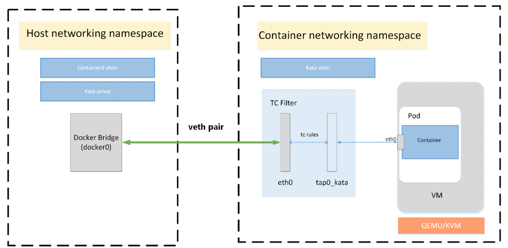
With TC filter in place, a redirection is created between the container network and the virtual machine. As an example, the CNI may create a device, eth0, in the container’s network namespace, which is a VETH device. Kata Containers will create a tap device for the VM, tap0_kata, and setup a TC redirection filter to mirror traffic from eth0’s ingress to tap0_kata’s egress, and a second to mirror traffic from tap0_kata’s ingress to eth0’s egress.
Storage
Container workloads are shared with the virtualized environment through 9pfs. The devicemapper storage driver is a special case. The driver uses dedicated block devices rather than formatted filesystems, and operates at the block level rather than the file level. This knowledge is used to directly use the underlying block device instead of the overlay file system for the container root file system. The block device maps to the top read-write layer for the overlay. This approach gives much better I/O performance compared to using 9pfs to share the container file system.
3.3 k8s + docker
3.4 k8s + kata
Reference: https://github.com/kata-containers/documentation/blob/master/design/architecture.md
The container process is then spawned by agent, an agent process running as a daemon inside the virtual machine. kata-agent runs a gRPC server in the guest using a VIRTIO serial or VSOCK interface which QEMU exposes as a socket file on the host. kata-runtime uses a gRPC protocol to communicate with the agent. This protocol allows the runtime to send container management commands to the agent. The protocol is also used to carry the I/O streams (stdout, stderr, stdin) between the containers and the manage engines (e.g. Docker Engine).
VSOCK
VM Sockets allows communication between virtual machines and the hypervisor. User level applications both in a virtual machine and on the host can use the VM Sockets API, which facilitates fast and efficient communication between guest virtual machines and their host. A socket address family, designed to be compatible with UDP and TCP at the interface level, is provided.
####VIRTIO
Reference: https://developer.ibm.com/articles/l-virtio/
In a nutshell, virtio is an abstraction layer over devices in a paravirtualized hypervisor. virtio was developed by Rusty Russell in support of his own virtualization solution called lguest.
Let’s start with a quick discussion of two distinct types of virtualization schemes: full virtualization and paravirtualization. In full virtualization, the guest operating system runs on top of a hypervisor that sits on the bare metal. 1](https://developer.ibm.com/articles/l-virtio/#fig1)).
In the full virtualization scheme, the hypervisor must emulate device hardware, which is emulating at the lowest level of the conversation (for example, to a network driver). Although the emulation is clean at this abstraction, it’s also the most inefficient and highly complicated. In the paravirtualization scheme, the guest and the hypervisor can work cooperatively to make this emulation efficient. The downside to the paravirtualization approach is that the operating system is aware that it’s being virtualized and requires modifications to work.
Figure 1. Device emulation in full virtualization and paravirtualization environments
Hardware continues to change with virtualization. New processors incorporate advanced instructions to make guest operating systems and hypervisor transitions more efficient. And hardware continues to change for input/output (I/O) virtualization, as well (see resources on the right to learn about Peripheral Controller Interconnect [PCI] passthrough and single- and multi-root I/O virtualization).
But in traditional full virtualization environments, the hypervisor must trap these requests, and then emulate the behaviors of real hardware. Although doing so provides the greatest flexibility (namely, running an unmodified operating system), it does introduce inefficiency (see the left side of Figure 1). The right side of Figure 1 shows the paravirtualization case. Here, the guest operating system is aware that it’s running on a hypervisor and includes drivers that act as the front end. The hypervisor implements the back-end drivers for the particular device emulation. These front-end and back-end drivers are where virtio comes in, providing a standardized interface for the development of emulated device access to propagate code reuse and increase efficiency.
In addition to the front-end drivers (implemented in the guest operating system) and the back-end drivers (implemented in the hypervisor), virtio defines two layers to support guest-to-hypervisor communication. At the top level (called virtio) is the virtual queue interface that conceptually attaches front-end drivers to back-end drivers. Drivers can use zero or more queues, depending on their need. For example, the virtio network driver uses two virtual queues (one for receive and one for transmit), where the virtio block driver uses only one. Virtual queues, being virtual, are actually as implemented rings to traverse the guest-to-hypervisor transition. But this could be implemented any way, as long as both the guest and hypervisor implement it in the same way.
Figure 3. High-level architecture of the virtio framework
As shown in Figure 3, five front-end drivers are listed for block devices (such as disks), network devices, PCI emulation, a balloon driver (for dynamically managing guest memory usage), and a console driver. Each front-end driver has a corresponding back-end driver in the hypervisor.